

D02- Return of the Snake
Abstract
Abstract
Abstract:
This project presents an FPGA-based implementation of the retro Snake Game using Verilog HDL. The objective is to showcase the capabilities of FPGA platforms in real-time, interactive digital environments. The game logic, including snake movement, apple generation, and collision detection, is entirely implemented in hardware, leveraging combinational and sequential logic, finite state machines (FSMs), and peripheral interfacing. The game is displayed on a VGA-compatible monitor, interfaced with the FPGA. The project serves as a practical exploration of hardware-software integration, digital design principles, and real-time embedded systems, making it an engaging demonstration of FPGA-based gaming applications.
Introduction:
The Snake Game is a classic arcade game that challenges players to control a growing snake while maneuvering around obstacles and avoiding collisions. Originally introduced in early arcade machines and later popularized on mobile phones, the game provides an excellent case study for real-time digital design.
This project implements the retro Snake Game on the Nexys4 Artix 7 DDR FPGA board using Verilog HDL, displaying it on a VGA compatible monitor. Unlike software-based implementations that rely on microcontrollers or processors, this version of the game is entirely hardware-driven. The FPGA directly handles user input, game logic, collision detection, and VGA output generation. This approach ensures low-latency gameplay and serves as a hands-on demonstration of FPGA capabilities in real-time digital systems.
The project involves the design and implementation of game mechanics, video signal generation for a VGA display, and hardware interfacing with input peripherals. By integrating these components, we explore various digital design concepts such as finite state machines (FSMs), combinational and sequential logic, memory handling, and real-time signal processing.
Methodology:
Description of the Game
The Snake game is a classic arcade-style game where the player controls a snake that continuously moves around a grid-based playfield. The objective is to consume randomly appearing food items, which cause the snake to grow in length, while avoiding collisions with itself and the boundaries of the play area. The game becomes progressively more challenging as the snake lengthens, requiring careful navigation to maximize the score before an inevitable collision ends the game.
The snake’s movement is controlled in four directions—up, down, left, and right—using external input devices such as buttons or switches. Once a direction is chosen, the snake moves continuously until the player changes it. The movement follows a fixed update rate, dictated by a clock signal, ensuring a smooth and consistent gameplay experience. The snake’s body is represented as a series of segments, with each segment following the previous one as the snake advances. When the snake’s head reaches a food item, the food is consumed, and the snake’s length increases by adding a new segment at its tail. A new food item is then randomly placed at an unoccupied position within the play area. This process continues, challenging the player to control the snake’s movements carefully to avoid running into itself or the game boundaries. The score increases with each food item consumed, adding an element of competition and progression.
Collision detection is a critical aspect of the game. The system continuously checks if the snake’s head has collided with either the edges of the screen or its own body. If a collision is detected, the game ends, and the final score is displayed. Implementing this logic in hardware requires efficient state machine design and real-time memory management to track the positions of all snake segments.
Implementation:
The Snake game is implemented entirely in hardware using Verilog HDL on a Nexys4 Artix 7 DDR FPGA board. The game logic is structured using finite state machines (FSMs) to control snake movement, food generation, and collision detection. A register-based memory system tracks the snake’s position on a grid, with each movement updating the coordinates accordingly. The VGA controller, implemented within the FPGA, generates the necessary synchronization signals to display the game on a monitor. The snake, food, and boundaries are rendered by mapping their respective positions to pixel coordinates on the screen. The game runs at a fixed clock cycle, synchronizing all operations, including movement updates and display refresh rates, ensuring smooth gameplay.
Hardware:
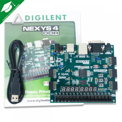
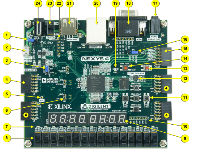
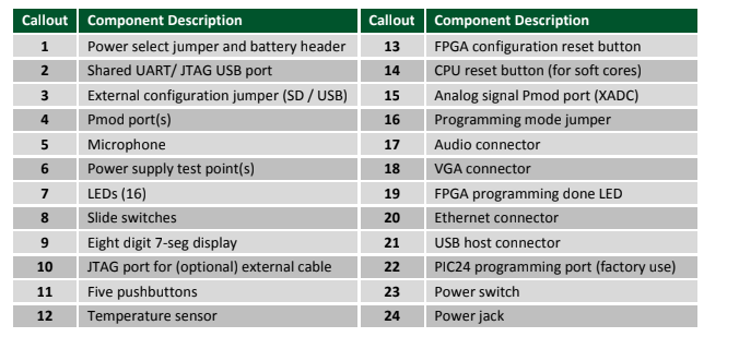
The system is implemented on a Nexys4 Artix 7 DDR FPGA board. The Nexys 4 board is a complete, ready-to-use digital circuit development platform based on the latest Artix-7TM Field Programmable Gate Array (FPGA) from Xilinx. With its large, high-capacity FPGA (Xilinx part number XC7A100TCSG324), generous external memories, and collection of USB, Ethernet, and other ports, the Nexys 4 can host designs ranging from introductory combinational circuits to powerful embedded processors. Several built-in peripherals, including an accelerometer, temperature sensor, MEMs digital microphone, a speaker amplifier, and a lot of I/O devices allow the Nexys 4 to be used for a wide range of designs without needing any other components. The Nexys 4 FPGA board includes the following ports and peripherals:
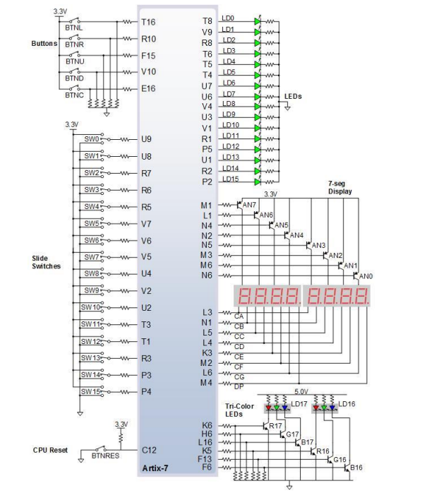
• User Interface & Display:
– 16 user switches
– 16 user LEDs
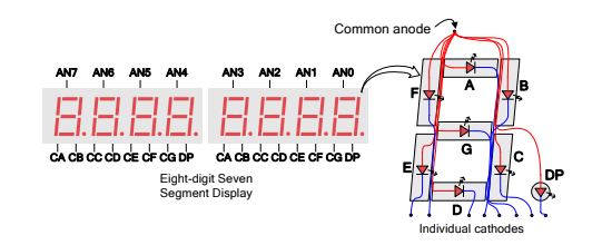
– Two 4-digit 7-segment displays
– Two tri-color LEDs
• Communication & Storage:
– USB-UART Bridge
– Micro SD card connector
– Serial Flash
– 16Mbyte CellularRAM
– Digilent USB-JTAG port for FPGA programming and communication
– USB HID Host for mice, keyboards, and memory sticks
• Graphics & Audio:
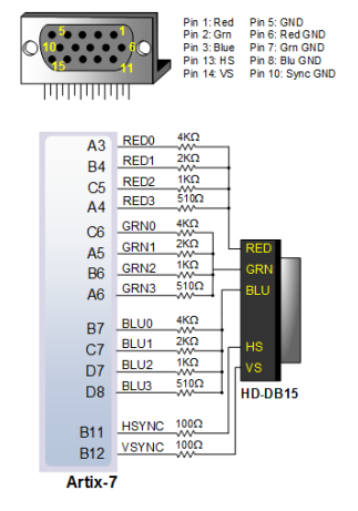
– 12-bit VGA output
– PWM audio output
– PDM microphone
• Sensors & Connectivity:
– 3-axis accelerometer
– Temperature sensor
– 10/100 Ethernet PHY
• Expansion & Interfacing:
– Four Pmod ports
– Pmod for XADC signals
Verilog HDL Hardware:
SnakeTop.v
The snake_top module is the top-level module that controls the Snake game on an FPGA, integrating various subsystems such as VGA display, score display, sound, and snake position handling. It interfaces with several components, including VGA signals, audio output, and seven-segment displays for score visualization. The module has input ports for button controls, clock signals, and reset, and output ports for VGA color signals (vga_r, vga_g, vga_b), sync signals (hsync, vsync), audio (AUD_PWM, AUD_SD), and seven-segment display signals (AN, seg).
Within the snake_top module, various submodules are instantiated to perform specific tasks. For example, the Snake_Position_Controller module handles the movement and collision detection of the snake. The Random_Generator module generates random positions for the apples that the snake consumes. The vga_controller module generates the video signal for the VGA display based on the snake’s position and color. Clock dividers like Clock_Divider_1s, Clock_Divider_2, and Clock_Divider_25Mhz are used to generate slower clocks for different operations, ensuring proper timing for game updates and display.
The game mechanics include apple consumption, score updates, and snake length growth. When the snake’s head position (head_x and head_y) aligns with the apple’s position (curr_apple_x and curr_apple_y), the apple_eaten flag is set, and the snake’s length and score are incremented. The score is calculated based on the snake’s velocity and apple consumption rate. The highest score achieved is also tracked and displayed. The game logic continuously updates the snake’s position and checks for collisions.
The scoreboard is displayed using a 7-segment display, where the score and high score are displayed in a human-readable format. The disp_7_seg module controls the 7-segment display by selecting the correct digit based on the current score or high score. The play_sound module generates a sound whenever the snake eats an apple, enhancing the gaming experience.
Clock Divider 2.v
The Clock_Divider_2 module is used to generate clocks with different frequencies from the FPGA’s 100 MHz system clock. The module generates two primary output clocks: a 25 MHz clock for controlling the 7-segment displays and a 1 Hz clock for controlling the movement of the snake in the game. The module reduces the 100 MHz clock by dividing it down to the required frequencies using simple counters. This is necessary as different components of the game require different clock rates for synchronization. The 25 MHz clock ensures that the display is updated at a frequency suitable for visual perception, while the 1 Hz clock is used to regulate the snake’s movement speed.
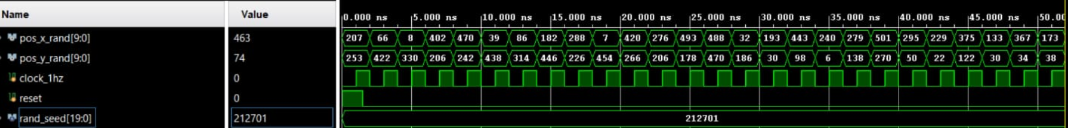
Random Generator.v
The Random_Generator module generates random coordinates for the apple’s position in the game using a Linear Feedback Shift Register (LFSR). The module takes a 1 Hz clock, a reset signal, and the current position of the apple as inputs. It uses the 20-bit seed (rand_seed) to generate pseudo-random values for the apple’s position on the screen. The LFSR operates by shifting the bits and applying an XOR operation to produce a new random value. The module ensures that the apple’s position does not overlap with the snake’s body, walls, or restricted areas on the screen. It uses the generated x and y coordinates to place the apple at a random but valid position within the game’s play area.
Snake Position Controller.v
The Snake_Position_Controller module controls the movement of the snake in the game. The module takes the current position of the snake’s body, the velocity of the snake in the x and y directions, and the input from the direction buttons as inputs. It uses this information to update the snake’s position based on the velocities. The movement is handled by shifting the positions in an array, which holds the coordinates of the snake’s body. When the snake eats an apple, the body array is updated, and the head of the snake is moved to the position of the apple. The module also checks for collisions with the body and boundaries. If a collision is detected, the game will end. The module ensures the snake moves smoothly and updates its position on the screen.
go generator.v
The go_generator module is responsible for generating a 16-bit output signal based on an 8-bit input value. The output data is used to represent graphical patterns, likely for visual display purposes. The module operates by reading the value input on every positive clock edge, and using a case statement to select a predefined 16-bit pattern corresponding to the input value. Each pattern represents a different character or symbol that might be displayed, for example, as part of a game or on a seven-segment display. The patterns cover different graphical shapes like the letter ”G”, ”A”, ”M”, ”E”, and so on, with each letter or shape mapped to an 8-bit input code.
In essence, the go_generator module allows for dynamic generation of visual representations based on input data, making it highly useful in applications like character or game display systems. As the clock progresses, the data output is updated to reflect the input value, enabling real-time visual updates on the display. This module’s flexibility in handling different input values ensures that a variety of graphical symbols can be generated using a relatively simple 8-bit input.
textgenerator.v
The textgenerator.v module is designed to generate a graphical representation of numbers (0-9) using 8-bit data patterns, which can be displayed on a device such as a 7-segment display. The module takes in an 8-bit input value and outputs an 8-bit data signal that represents the visual pattern corresponding to the given number. On each rising edge of the clock signal clk, the module evaluates the value input through a case statement, where each possible input (ranging from 8’b00010000 to 8’b10101001) maps to a specific 8-bit pattern that visually represents a digit in a pixel-based format. For example, the value 8’b00010000 corresponds to the number ”0” and outputs the pattern 8’b00111100, which illuminates the appropriate segments to display ”0”. Similarly, other values correspond to the respective 8-bit patterns for digits 1-9. This allows the module to drive displays that visualize numbers or characters based on the given input value.
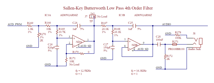
play sound.v
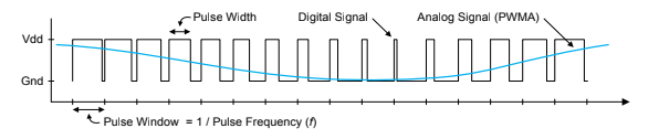
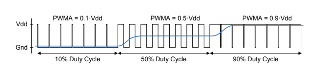
The play_sound module generates a Pulse Width Modulation (PWM) signal to control audio output, making it suitable for generating sound effects in embedded systems, like alarms or notifications. The module uses a 20-bit counter (counter) to control the timing of the PWM signal. When the counter reaches a predefined value (113635), it resets to zero and toggles the state of the clk_stb signal. This control signal (clk_stb) is then used to toggle the AUD_PWM signal, which is the actual PWM signal controlling the audio output.
The module also includes an Alarm input, which directly controls the AUD_SD output signal. This could be used to turn the sound on or off based on the alarm state. As a result, the play_sound module is designed to produce periodic audio signals (such as a beep or tone) that can be used for audible alerts in embedded applications. The frequency of the sound is determined by the clock signal and the counter, allowing for configurable sound generation.
disp_7_seg.v
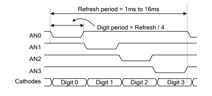
The disp_7_seg module controls the refresh and data display mechanism for a multi-digit 7-segment display. It combines two primary functionalities: digit selection and segment control. A 20-bit counter (rr) is used to generate the refresh rate for the display. The upper three bits of this counter (rr[19:17]) serve as the selector for which digit is currently being activated and are passed to the anode_sel module to manage the active anode. Concurrently, the 5-bit digit_holder input is mapped to the corresponding 7-segment display pattern through the seg_mapping module. The combination of time-multiplexed anode control and synchronized segment mapping enables efficient and flicker-free visualization of numerical values on the 7-segment display, with minimal hardware and no need for separate clock dividers.
seg mapping.v
The seg_mapping module is designed to convert a 5-bit input (digit_holder) into a corresponding 7-segment display pattern (seg). Seven-segment displays are commonly used in digital clocks, calculators, and similar devices to display numerical and alphanumeric characters. This module maps each of the possible 5-bit inputs to a specific 7-bit output that drives the segments of the display. Each digit_holder value (ranging from 5’b00000 to 5’b10001) corresponds to a specific pattern of segments that should be turned on or off to display a particular character or state.
The functionality of the seg_mapping module is implemented using a case statement, where each input value generates a specific 7-segment pattern. For example, 5’b00000 corresponds to the pattern 7’b0000001, which represents the digit ”0” on a 7-segment display. Similarly, other patterns are mapped for digits like ”1”, ”2”, ”3”, and special states such as ”blank” or ”off” (e.g., 5’b10000 maps to all segments turned off, 7’b1111111). This module is essential for driving visual outputs on 7- segment displays, and it helps ensure that the appropriate digits or symbols are displayed according to the input value.

anode_sel.v
The anode_sel module is responsible for activating one of the eight digits of a 7-segment display at a time using a time-multiplexed approach. The module takes in a 3-bit input signal rr, which serves as a rotating counter to determine which digit is currently active. Based on the value of rr, the module sets the AN output—a one-hot encoded 8-bit signal where only one bit is pulled low at a time to activate the corresponding digit (due to the active-low configuration of the anodes). This digit cycling occurs at a sufficiently high frequency such that all digits appear to be lit simultaneously to the human eye, enabling smooth and consistent multi-digit display operation.
vgacontroller.v
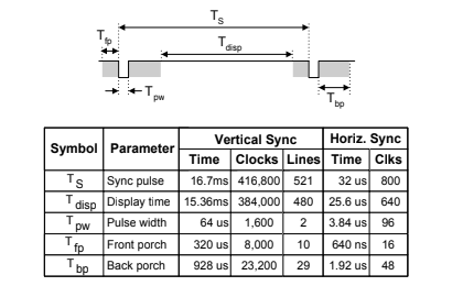
The vgacontroller.v module generates VGA synchronization signals (hsync and vsync) for a 640x480 resolution display at 60Hz. The code uses a 25 MHz clock for timing and includes counters for horizontal (h_counter) and vertical (v_counter) pixel positions. It also handles RGB color output based on the coordinates of the snake and apple. The snake is represented as a series of small blocks, and its movement is controlled by the velocity (last_vel_x and last_vel_y). The VGA controller draws the snake (head in yellow and body in red) based on input coordinates and updates the screen accordingly. The design supports score and game-over displays through external modules like score_generator and go_generator. The snake’s position and behavior are checked based on input coordinates, and the controller generates corresponding color signals for the VGA output.
Results:
Implementing the Return of Snake game on an FPGA using VGA output was successfully completed. The results of the project are summarized as follows:
Gameplay Performance
• The snake’s movement is responsive to user input with minimal latency.
• The VGA display correctly renders the game elements, including the snake, food, and boundaries, with clear pixel mapping.
VGA Output
• The resolution achieved was 640x480 at 60Hz, adhering to the standard VGA timing specifications.
• Color encoding was successfully implemented, allowing distinct colors for the snake, food, and background.
• The grid-based layout was accurately mapped to the screen, ensuring proportional scaling.
FPGA Resource Utilization
• Memory blocks were efficiently managed for storing game states and rendering frames.
• The VGA synchronization signals were successfully generated without glitches.
Game Features
• The snake grows correctly upon consuming food, and food is randomly repositioned within the play area.
• Collision detection functions correctly, detecting boundary hits and self-collisions to end the game.
• Score tracking was successfully implemented and displayed on the screen.
User Input and Controls
• The game supports real-time user input via push buttons on FPGA.
• Directional changes are registered instantly, ensuring smooth gameplay.

Testing and Debugging:
Milestone 1: Initial snake movement
Successfully implemented basic snake motion using finite state machines and clock-controlled updates, laying the foundation for real-time gameplay.
Milestone 2: Extension of the snake
Implemented logic to dynamically grow the snake's length upon apple consumption, maintaining smooth movement and accurate body tracking.
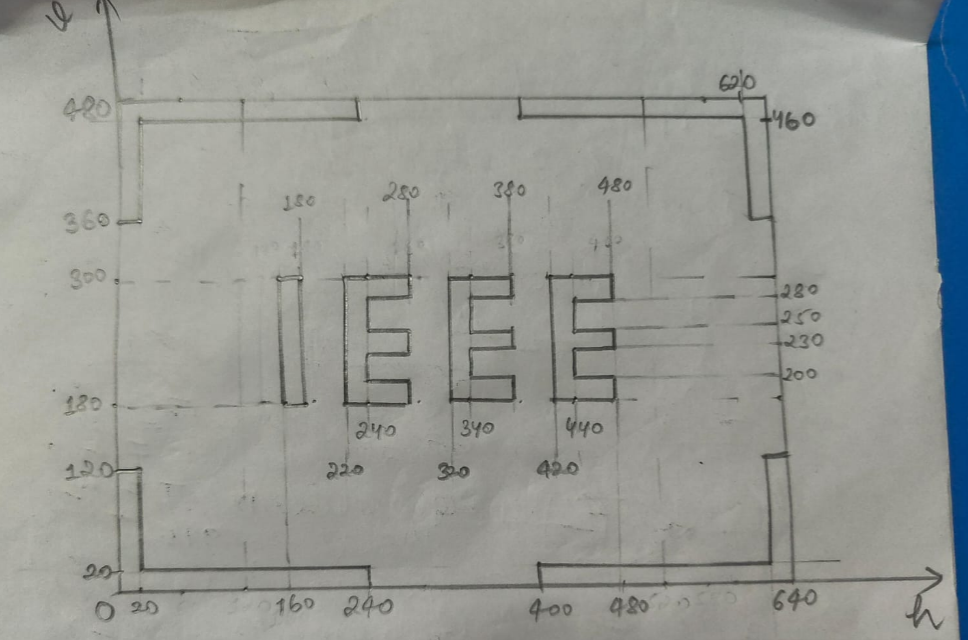
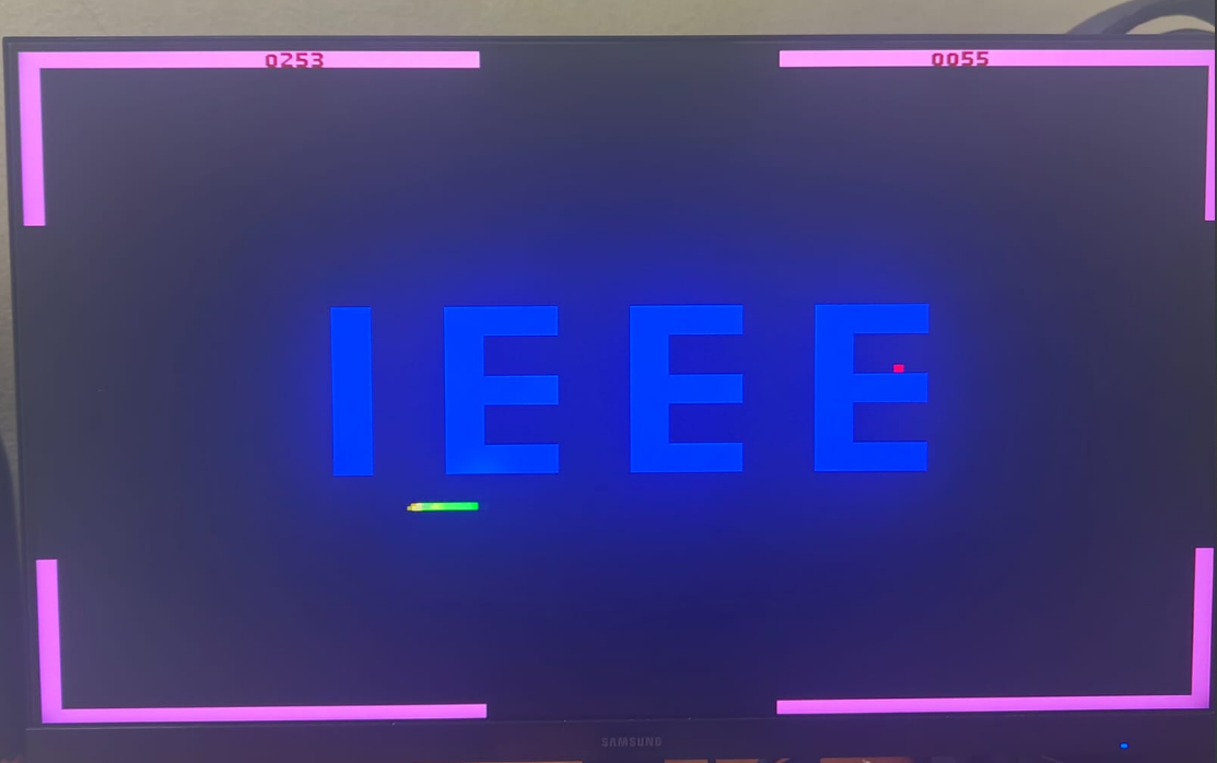
Milestone 3: Adding IEEE logo and walls
Added the IEEE logo and game walls to the display, which act as obstacles for the snake.
Milestone 4: Collision mechanics
Implemented collision detection mechanisms, triggering game over upon the snake's contact with boundaries or its own body.
Milestone 5: Dynamic Walls
Implemented moving and score-dependent wall patterns to introduce variability and challenge.
Milestone 6: Integrating Scoreboard on screen
Displayed the real-time score and high score directly on the VGA output.
Milestone 7: Adding sound effects
Integrated audio output to play distinct sound cues for key events like apple collection, wall collision, and game over.
Future Scope:
1. Difficulty Levels with Dynamic Speed and Scoring
Introducing difficulty levels can make the game more engaging. Each level would correspond to a different snake movement speed and scoring mechanism. For example, higher difficulty levels could increase the snake’s speed and reward more points per apple collected, offering a challenging yet rewarding experience for advanced players.
2. PS/2 Keyboard Integration for Controls
Currently, direction control is handled through physical pushbuttons on the FPGA board. A more versatile approach would be interfacing a PS/2 keyboard with the FPGA to allow standard directional key inputs.
3. Audio Feedback for Game Events
Adding audio output through a PWM-based module or using onboard audio hardware can enhance the sensory appeal of the game. Distinct sounds can be played for various in-game events such as apple collection, game over, etc.
4. Super Apple
A time-sensitive "super apple" feature can be added to introduce a new gameplay dynamic. This special apple would appear occasionally on the screen, offering bonus points if collected within a short duration.
References:
Nishant Singla, Mandeep Singh Narula, “FPGA Implementation of Snake Game Using Verilog HDL”, May 2018 (https://drive.google.com/file/d/1cGgnBA8dDdktOeK71ILNqDV473CABYY8/view?usp=drivesdk)
YouTube: Verilog Snake Game on FPGA (https://youtu.be/fJycFrYZnUM?feature=shared)
YouTube: Snake game using FPGA board and Verilog (https://youtu.be/yVLQgiavj5I?feature=shared)
Repository:
All the source codes, constraints and simulation files can be found here.
All the implementation and synthesis reports can be found here.
Mentors:
Madhav Kedia
Rohan Abhilash S.
Omkar Chougule
Mentees:
Tarun Sirigiri
Tejhuram Ravichandran
Rupan
Report Information
Team Members
Team Members
Report Details
Created: April 7, 2025, 12:05 a.m.
Approved by: Omkar Patil [Diode]
Approval date: April 7, 2025, 3:29 p.m.
Report Details
Created: April 7, 2025, 12:05 a.m.
Approved by: Omkar Patil [Diode]
Approval date: April 7, 2025, 3:29 p.m.